
Upright lines · light and medium gauge
Rack Upright Machine for 1.5 – 2.5 mm Strip
Rack upright roll forming machines for 1.5 – 2.5 mm strip produce the Omega-section column used in selective and medium-duty pallet racking, punching the tear-drop and butterfly holes on line and cutting to length in one pass. At this thickness the difficulty is not forming force — it is holding the section without marking the strip and keeping the hole pattern square to the cut end.
- Strip range on this build
- 1.5 – 3.0 mm
- Forming stations
- 18
- Main motor
- 15 kW
- Line speed
- up to 15 m/min
What changes when the strip is thin
Below about 2.5 mm the forming load stops being the constraint and three other things take over. The first is marking: thin strip takes every roll mark, and a painted upright shows it. The second is twist, because a light section has less material to resist it and the roll set has to be aligned more precisely than the tonnage suggests. The third is the hole pattern, which is punched before forming and then stretched by it — a pattern that is right on the flat strip can be out of position on the formed column.
All three are solved in the tooling and the setup rather than by adding power. That is why a light-gauge upright line is not simply a heavy line with a smaller motor: the roll pitch, the roll surface finish and the punch clearance are all specified for the thickness it was built around.
What changes across the light and medium gauge band
| At 1.5 mm | At 2.0 mm | At 2.5 mm |
|---|---|---|
| Roll pitch kept short to avoid marking | Standard roll pitch | Roll pitch and gap set for springback |
| Punch clearance at the low end of the range | Nominal punch clearance | Clearance opened to suit the thicker strip |
| Light strip guides; more attention to twist | Standard guides | Heavier guides, camber checked on first article |
| 18 stations is generous for the section | 18 stations covers it | 18 stations still covers it, at lower speed |
The 18-station, 15 kW build covers 1.5 – 3.0 mm. Below 1.5 mm the section usually changes, and so does the roll set.
Why the hole pattern is the real specification
On a selective racking upright the tear-drop and butterfly holes are what the beam connectors lock into, so their pitch and their position relative to the section centreline are functional dimensions, not cosmetic ones. An upright that is 0.5 mm out over a 2 m pitch will still assemble — once. Over a bay of frames it will not.
Check the pattern two ways before the machine ships: on the flat strip before forming, and on the finished column after forming. The difference between the two numbers is the forming stretch, and it is a property of your section, not of the machine. Once it is known, the punch tooling is set so the formed column lands on the drawing.
- Hole pitch measured over the full pattern, not between two adjacent holes.
- Edge distance from the section face, checked on the formed part.
- Hole shape after forming: a tear-drop that closes up has too little punch clearance.
- First-article record signed before the balance of the order is formed.
Output at this thickness
A 15 m/min line cutting 3.0 m uprights gives a theoretical 300 pieces an hour, and around 200 after changeover. Thin gauge does not change that arithmetic — it changes how often you have to stop. Light sections are usually ordered in more sizes than heavy ones, so the changeover allowance on a light-gauge line is normally worse than on a heavy line running one section.
If your order book is a mix of three or four upright widths, price the second roll set and the second punch set with the machine. Buying them later costs more and takes the line out of production twice.
Machines for this job
The builds that cover it
Each of these is a standard build quoted against your drawing, not a catalogue item. Where none of them fits, the custom range starts from the same components.
-
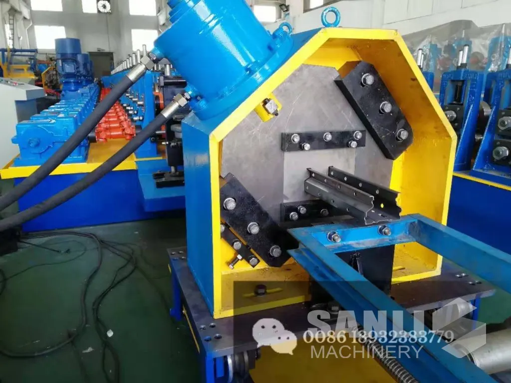
Rack Upright Roll Forming Machine
The 1.5 – 3.0 mm build: 18 stations, 15 kW, holes punched on line. Covers this band with headroom.
View machine -
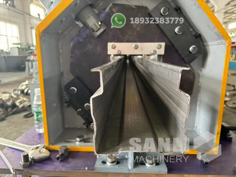
Heavy Duty Rack Upright Roll Forming Machine
Sized for 2.0 mm selective racking: 20 stations, twin 22 kW motors, gearbox drive.
View machine -
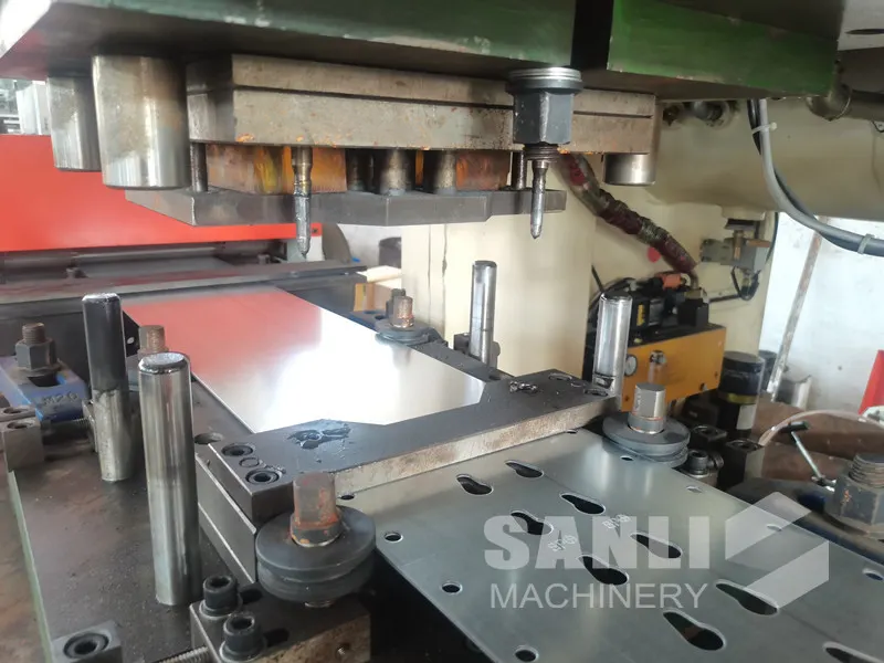
Punch Mould for Rack Upright
The tooling side: SKD11 dies with inserted lower die, 1.5 – 3.5 mm, made to your hole drawing.
View machine
The other side
When this is not the right build
The light-gauge build is the right answer for most selective racking. It is the wrong answer in these cases.
You regularly form 3.0 mm
The 18-station, 15 kW machine reaches 3.0 mm, but continuously forming at the top of its range is not the same as being built for it. The heavy-duty build carries twin 22 kW motors and Cr12 rolls for that work.
The uprights are for AS/RS
Automated storage columns are judged on straightness and twist over the full column height, which puts the machine in a different accuracy class. Buy for the tolerance, not for the thickness.
You want one line to cover 1.5 mm to 3.0 mm equally
One machine can cover the range, but it will be set up for one part of it. If both ends of the range are in production at the same time, two builds or two roll sets are the honest answer.
Before you order
Questions this page usually raises
Can a 1.5 – 3.0 mm machine run 1.2 mm strip?
Mechanically it can pass the strip, but the roll set and punch clearance are set for the thicker range, and 1.2 mm will mark and twist in rolls designed around 2 mm. Below 1.5 mm the section usually changes anyway, so the practical answer is a roll set specified for that thickness rather than a wider range on the same rolls.
How many stations does a 2.0 mm upright need?
The 2.0 mm selective racking build we supply runs 20 stations with twin 22 kW motors. The 1.5 – 3.0 mm general build runs 18 stations on a single 15 kW motor. Station count follows the number of bends and the roll pitch needed to form them without marking, not the thickness alone.
Is the punching station before or after forming?
Before. The strip is punched flat, then formed, which is what allows the hole pattern to be held to the same datum as the cut length and removes a handling step. The punch tooling is set to compensate for the stretch the forming passes add, so the finished column matches your drawing.
What strip width can the line take?
Width follows the section, and the section follows your drawing. Send the developed width and the coil weight you buy, and the decoiler, guides and roll set are specified around both. The strip width is not a fixed limit on the machine — it is fixed at order.
Other selection guides
Selection guides
Head to head
Send the drawing and the output you need
The section drawing, the strip grade and the pieces per shift are enough to specify the machine — and enough to tell you if a different configuration would serve you better.