
Selection guide
How to Choose a Rack Roll Forming Machine
Five decisions fix most of the cost of a rack roll forming line: the component you are forming, the strip thickness and grade, the output you actually need, where the holes are punched, and how much of the line one operator has to run. This page works through each one in the order that changes the machine.
- Strip thickness covered
- 0.4 – 3.0 mm
- Forming stations
- 13 – 30
- Main motor
- 15 – 44 kW
- Standard line speed
- 5 – 15 m/min
Start from the part, not from the machine
A pallet racking frame is five parts: the upright, the beam, the bracing, the shelf or decking panel, and the connectors that join them. Each part is formed on a different line, and the lines are not interchangeable. A bracing machine cannot form an upright, and an upright line set up for 2.5 mm strip will not run a 0.6 mm shelf panel without a different roll set. So the first question is not which machine to buy, but which part you need to make in house first.
Most racking plants start with the upright, because it carries the longest setup and because a subcontractor is least likely to hold your exact hole layout. Beams come next, then bracing, then shelf panels. If you are adding capacity rather than starting from zero, work backwards from the part that is currently delaying deliveries — that is the part with a queue in front of it.
The five rack components and the machine that forms each
| Component | Typical strip | Stations | Main motor | What sets the build |
|---|---|---|---|---|
| Upright | 1.5 – 3.0 mm | 18 – 20 | 15 – 44 kW | Hole pattern and column straightness |
| Box beam | 1.5 – 2.0 mm | 14 – 16 | 22 kW | Closing the seam after forming |
| Step beam | 1.2 – 1.6 mm | 23 | 30 kW | Two-plane flange, fly saw cut |
| Bracing | 1.4 – 1.8 mm | 13 | Per build | Part count per frame, not complexity |
| Shelf panel | 0.4 – 1.2 mm | 30 | Per build | Thin gauge needs short roll pitch |
Ranges are the builds we quote most often, not the limits of what can be built.
Strip thickness decides the build, not the price list
Forming load rises roughly with the square of strip thickness. Going from 1.5 mm to 3.0 mm doubles the thickness and multiplies the load on the rolls, shafts and housing by about four. That single ratio explains most of the difference between two machines that look the same in a photograph: the 3.0 mm upright line carries two 22 kW main motors, Ø80 mm shafts, Cr12 rolls at HRC 58 – 62 and a gearbox drive, while a machine built around 1.5 mm strip runs one 15 kW motor on 40Cr shafts.
This is also why a supplier who quotes one price for an upright machine is telling you the price of a specific thickness range, whether or not they say so. Ask for the range in writing, and ask what changes above it.
- Motor power, and whether the drive is one motor or two — a twin-motor build is the usual sign of a 3.0 mm machine.
- Shaft diameter: Ø80 mm shafts appear on heavy builds because deflection at the rolls is what limits section accuracy.
- Roll material and hardness: GCr15 on light and medium builds, Cr12 at HRC 58 – 62 where 3 mm strip is formed continuously.
- Drive type: chain drive is common up to about 2 mm, gearbox drive on the heavier upright lines.
- Cut-off force: a 3.0 mm upright needs roughly three times the cutting force of a 1.5 mm one.
Output: what 15 m/min actually means
Line speed is quoted as metres of strip per minute, which is not the number a production manager needs. Convert it before comparing quotes. At 15 m/min with a 3.0 m finished upright, the arithmetic gives 300 pieces an hour. Allow 65 – 70% for coil changes, hole-pattern changes and cut-off stops, and the number to plan around is closer to 200.
The figure that decides whether top speed is worth paying for is changeover, not speed. If you run one section for a week at a time, top speed is the real constraint. If you change section or hole pitch twice a shift, setup time is the constraint, and a faster line will sit idle while the tooling is changed.
Rule of thumb at 3.0 m finished length, after changeover allowance
| Target output | What has to change | Where it goes wrong |
|---|---|---|
| Up to 150 pcs/h | Standard 15 m/min build, stop cut | Coil changes eat the gain |
| 150 – 250 pcs/h | Servo feed, quick-change punch tooling | Hole pattern change still costs a shift |
| 250 pcs/h and up | Flying cut, loop accumulator, longer run-out | Line length and capital both rise sharply |
A stop-cut line loses one cut length per cycle; a flying cut does not. That difference only matters above roughly 20 m/min.
Where the holes are punched
An upright can be punched on the roll forming line, before the forming stands, or afterwards on a separate press. On-line punching holds every hole to the same datum as the cut length, needs no second handling, and is the reason one operator can run an upright line. The cost is tooling: every hole pattern needs its own punch set, and a pattern change is a tooling change.
Post-punching on a press is cheaper to tool and easier to change, but the hole position is then measured from the cut end rather than formed into the part, and every upright passes through a second machine. For a plant making one or two patterns in volume, on-line punching is almost always the better answer. For a plant making short runs of many patterns, the tooling cost is the deciding factor.
How much of the line one operator runs
The gap between a manual and an automatic build is not in the forming section — it is coil handling, closed-loop control and whether the line stops itself when something is wrong. A fully automatic box beam line forms 1.5 – 2.0 mm strip through 16 stations at up to 15 m/min and runs from coil to cut length with no manual handling between steps, which is what lets one operator cover it.
If labour is cheap relative to capital where you build, a semi-automatic line is the better return. If labour is the constraint, the automatic build pays for itself in headcount rather than in speed.
Machines for this job
The builds that cover it
Each of these is a standard build quoted against your drawing, not a catalogue item. Where none of them fits, the custom range starts from the same components.
-
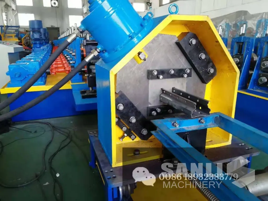
Rack Upright Roll Forming Machine
The machine most plants buy first: 1.5 – 3.0 mm, 18 stations, 15 kW, holes punched on line.
View machine -
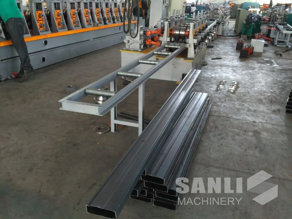
Rack Box Beam Roll Forming Machine
The beam volume case: 1.5 – 1.8 mm through 14 stations at up to 15 m/min, seam closed after forming.
View machine -
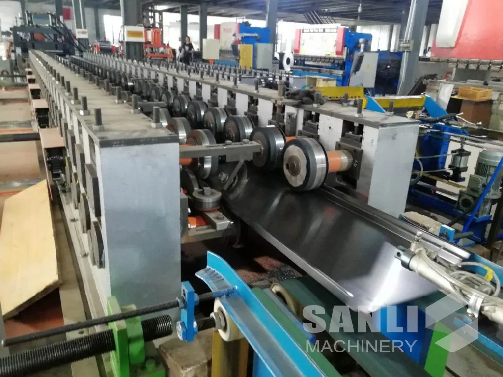
Rack Shelf Roll Forming Machine
Where thin gauge decides the build: 0.4 – 1.2 mm through 30 stations to keep the roll pitch short.
View machine
The other side
When a roll forming line is the wrong purchase
A line makes sense when you form the same family of profiles often enough to keep it loaded. These are the cases where it does not, and saying so is cheaper for both of us.
Under roughly 200 t of strip a year
The line will spend more time idle than forming. Buying formed profile from a specialist and concentrating on fabrication and powder coating usually returns the capital faster.
Many variants, very short runs
If each order is a different section depth, the roll change dominates the schedule and the machine becomes a liability. A press brake and bought profile cover the same orders without the tooling.
A one-off profile with no repeat order
Roll design and tooling are a fixed cost per profile. On a single order that cost lands entirely on that order. Ask for a sample run first, and only tool up when the second order arrives.
Before you order
Questions this page usually raises
How much does a rack roll forming machine cost?
Price is driven by five variables: the strip thickness range, the number of forming stations, whether punching is on the line, the cut-off type, and how automatic the line is. Those five can move the price further than most buyers expect, which is why we quote against a drawing and an output figure instead of publishing a price list. Send the section drawing, the material grade and the pieces per shift you need, and the quote will show which of the five is driving the number.
Can one machine run several upright widths?
Only where the sections differ in width and share the same hole layout and the same number of forming passes. A different section depth changes the roll set, and a different hole pattern changes the punch tooling. If you need two or three sizes on rotation, the practical answer is a quick-release roll set and a second punch set, quoted with the machine rather than added later.
Do you supply the punch tooling as well as the machine?
Yes. Upright punch moulds are SKD11 with an inserted lower die, covering 1.5 – 3.5 mm upright thickness, made to your hole drawing for pitch, hole shape and edge distance. The same tooling is supplied either as a standalone press tool or as the punching station on a roll forming line.
What lead time should I plan for?
Lead time is quoted per project because the long items are the forming rolls and the punch tooling, both of which are made to your drawing after the section is approved. The reliable way to compress the schedule is to freeze the section drawing early: every revision after roll design starts adds its own delay.
Selection guides and comparisons
Selection guides
Head to head
Send the drawing and the output you need
The section drawing, the strip grade and the pieces per shift are enough to specify the machine — and enough to tell you if a different configuration would serve you better.