
Upright lines · heavy gauge
Rack Upright Machine for 2.5 – 3.0 mm Strip
Heavy gauge rack upright roll forming machines form the thick-wall column used in high-bay, drive-in and AS/RS racking, where the column has to stay straight over a height a selective rack never reaches. At 2.5 – 3.0 mm the machine is built around forming load: twin main motors, Ø80 mm shafts, Cr12 rolls and a gearbox drive.
- Standard strip
- 2.0 mm, up to 3.0 mm
- Forming stations
- 20
- Main motor
- 22 kW × 2
- Hydraulic cut-off
- 11 kW
Why 3.0 mm is a different machine, not a bigger one
Forming load scales with the square of strip thickness. Going from 1.5 mm to 3.0 mm multiplies the load on the rolls and shafts by about four, and a machine sized for the first number will deflect under the second. Deflection at the roll gap shows up as a section that is right at the edges and wrong in the middle, which is why the heavy build starts with shaft diameter rather than with motor power.
The heavy-duty upright line runs 20 stations on two 22 kW main motors, on Ø80 mm shafts, with Cr12 rolls at HRC 58 – 62 and a gearbox drive. The rolls are Cr12 rather than GCr15 because 3.0 mm strip at production rate wears a GCr15 roll faster than most plants expect. The gearbox exists because a chain drive at this load is the part that fails first.
What the heavy build changes
| 2.0 mm build | 2.5 mm | 3.0 mm |
|---|---|---|
| 20 stations, twin 22 kW | 20 stations, twin 22 kW | 20 stations, twin 22 kW |
| Ø80 mm shafts | Ø80 mm shafts | Ø80 mm shafts, deflection checked at load |
| Cr12 rolls, HRC 58 – 62 | Cr12 rolls, HRC 58 – 62 | Cr12 rolls, hardness at the top of the band |
| 11 kW hydraulic cut-off | 11 kW cut-off | 11 kW cut-off at its working limit |
| 5 – 15 m/min | 5 – 15 m/min | 5 – 12 m/min in practice |
The machine is the same specification across the band; the speed and the tooling life are what change.
Straightness is the dimension that gets missed
A thick upright is bought for height, and height is where straightness stops being a detail. A column that is 1 mm out over 3 m is invisible in a selective rack and is a stacker crane clearance problem at 12 m. Camber and twist therefore have to be inspected over the full length of the finished column, on a bed, not by eye at the end of the line.
Agree the acceptance figure before the machine is built. A tolerance quoted at order is the only one that can be inspected at acceptance; a tolerance discussed afterwards is an argument. If your customer specifies a straightness figure, send it with the enquiry so the roll set and the straightener are specified around it.
- Camber measured over the full column length, not per metre.
- Twist checked with the column supported at both ends, not hanging.
- Cut end squareness: a bevelled cut reads as a bent column during assembly.
- Hole pattern position on the formed column, at the top and bottom of the length.
Cutting 3.0 mm strip
The cut-off is the second place heavy gauge shows up. Cutting 3.0 mm needs roughly three times the force of 1.5 mm, which is why the heavy line carries an 11 kW hydraulic cut-off rather than the 7.5 kW unit used on beam machines. A cut-off that is marginal shows as a burr on one side of the section and as blade wear that appears within weeks rather than months.
If the section is also being punched, check the punch tonnage against the same thickness. A 3.0 mm tear-drop needs a press and a tool that will hold up at that load; the punch moulds we supply cover 1.5 – 3.5 mm in SKD11 with an inserted lower die for exactly this reason.
Machines for this job
The builds that cover it
Each of these is a standard build quoted against your drawing, not a catalogue item. Where none of them fits, the custom range starts from the same components.
-
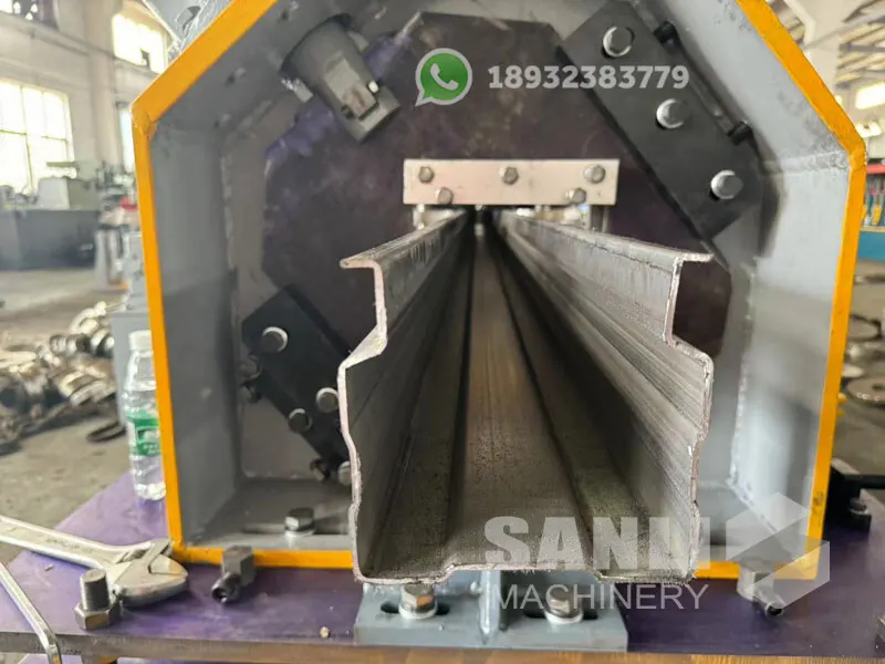
Heavy Duty Rack Upright Roll Forming Machine
Built for this band: 2.0 mm standard up to 3.0 mm, 20 stations, 22 kW × 2, Cr12 rolls.
View machine -
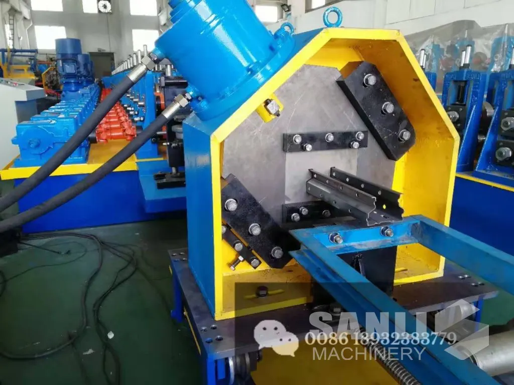
Rack Upright Roll Forming Machine
Where the heavy work is occasional: 1.5 – 3.0 mm on 18 stations and a single 15 kW motor.
View machine -
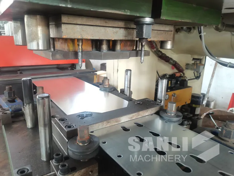
Punch Mould for Rack Upright
Punch tooling rated to 3.5 mm, SKD11 with inserted lower die, made to the hole drawing.
View machine
The other side
When the heavy build is money wasted
Paying for 3.0 mm capability you never use is a common way to overspend on an upright line.
Your strip never exceeds 2.0 mm
The 2.0 mm build does the same work on the same station count with the same drive arrangement. The saving is real and the parts are identical in use.
You buy 3.0 mm coil but form it once a quarter
Occasional heavy work does not justify a heavy machine if a subcontractor can form those sections. Keep the capital for the part you run every week.
The straightness requirement is the real problem
If the columns are for AS/RS, thickness is not the deciding specification — the accuracy class is. Buying a thicker machine does not buy tolerance; specifying for tolerance does.
Before you order
Questions this page usually raises
Can the line form 3.5 mm uprights?
The punch tooling covers 1.5 – 3.5 mm, but the forming section is a separate question. Above 3.0 mm the roll set, shaft diameter and motor sizing all move, and a stock heavy-duty machine should not be assumed to cover it. Send the section drawing and the strip grade before treating 3.5 mm as within range.
Why two main motors instead of one larger motor?
Two motors let the drive be split across the stand train, which keeps the load on each gearbox and shaft within tolerance and shortens the load path through the frame. One large motor on a single drive line concentrates the torque at the entry stands, which is where heavy-gauge machines tend to fail first.
What line speed should I expect at 3.0 mm?
The machine is quoted at 5 – 15 m/min and runs at the lower half of that range at 3.0 mm in production. Quoting the top of the range as a production figure is how suppliers win orders and lose them at acceptance — plan on the lower half and treat the top as headroom.
Does the heavy build handle high-tensile strip?
Yield strength matters as much as thickness: the same 3.0 mm section in a higher grade needs more forming load than the thickness alone suggests. Tell us the grade and the yield at enquiry, and the motor sizing is checked against it rather than against thickness.
Other selection guides
Selection guides
Head to head
Send the drawing and the output you need
The section drawing, the strip grade and the pieces per shift are enough to specify the machine — and enough to tell you if a different configuration would serve you better.